
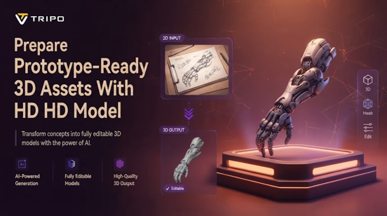
Sketch, photograph, and idea to prototype-ready models in minutes. Quickly creating assets allows designers to experiment with shapes, proportions, and directions before diving into in-depth modeling. But even generated geometry must be checked against dimensional, structural and prototype requirements during evaluation.
Selecting Images That Translate Well Into Prototype Geometry
It is easier to obtain better visual information from images with clear silhouettes and recognizable forms for image-based model generation. A clear image enables an AI 3d model generator to recognize the contours, proportions and parts. For simple objects with limited structural complexity and straightforward references, single-view images can be used. When depth, alignment and hidden relationships are relevant for the structural interpretation, multi-view references provide information. Ambiguous images can cause hidden surfaces, proportions, openings, joints and structural features to be distorted during generation. It is also helpful to have good lighting and clear backgrounds, which can help to make the important boundaries more obvious visually.
Balancing Geometry Detail With Prototype Requirements
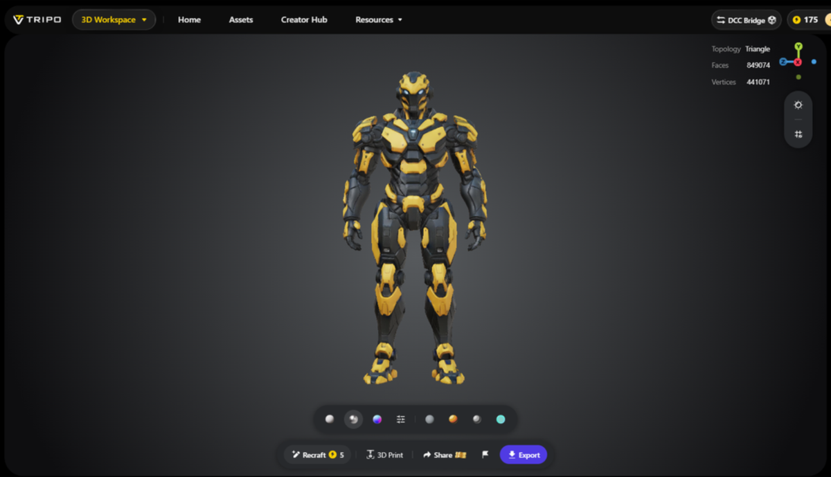
Polygon density should be proportional to the prototype’s purpose – not to the complexity of the geometry for each iteration. An image to 3d model process can generate detailed surfaces; complexity impacts editing. Low-poly meshes are good for fast geometry changes, visualization and for usage in applications that need efficient geometry in design. The more polygons, the more accurately curved edges, intricate contours and mechanical forms are represented. It is the optimal mesh that has been carefully balanced for the maximum amount of visible detail, editing flexibility and software requirements for most prototypes.
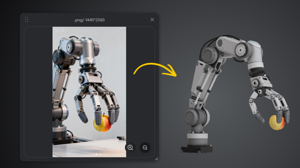
Steps to Prepare Prototypes Faster Using Image-to-3D Model Rapid Asset Generation
Step 1: Begin With a Reference Image
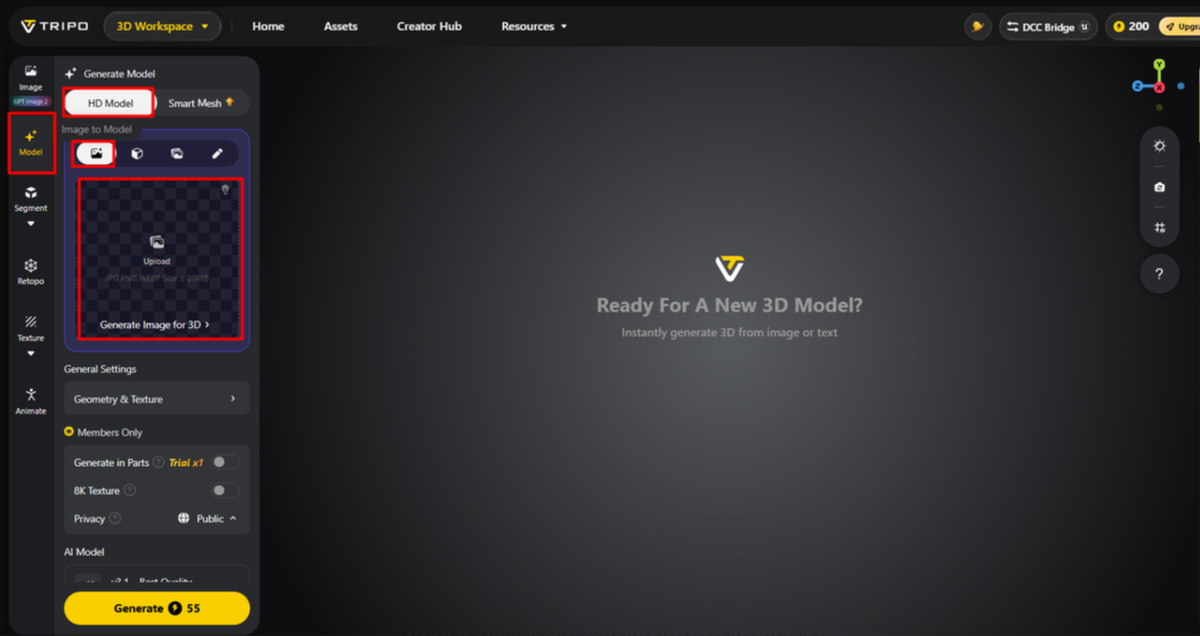
- First, access Tripo 3D and sign up. Go to the “Model” tab in the vertical left menu bar.
- Under “Generate Model”, choose “HD Model” to start creating your prototype asset. It will take several minutes to generate your model.
- Select the “Image to Model” tab. You can drag and drop your reference image into the workspace. You can also click “Upload” and select the image from a specific location on your device.
Step 2: Configure the Prototype Before Generation
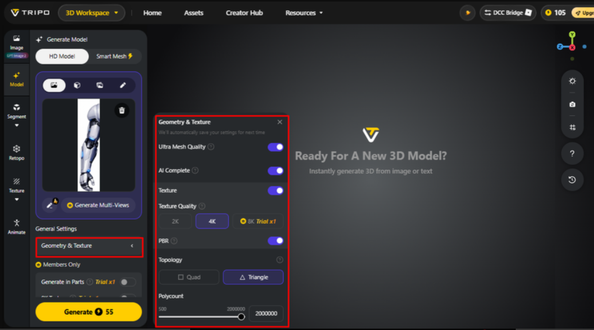
- Open “General settings” and customize “Geometry and Texture” for the prototype. Turn on “Ultra Mesh Quality” when you need a detailed and realistic model.
- With “AI Complete” enabled in the “Geometry & Texture panel”, AI can generate both the model’s geometry and texture for you. The option covers both tasks within that panel. Alternatively, activate texture generation and set your preferred “Texture Quality” to 2K, 4K, or 8K.
- Enable “PBR” when you want accurate material and reflective properties in the generated asset.
- Select “Quad” or “Triangle” topology based on the structure you want for your prototype.
- Set a custom polycount to control the mesh density and model complexity.
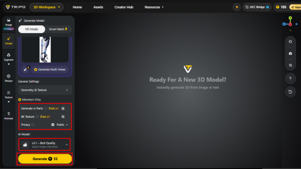
- Members can test “Generate in Parts”, “8K Texture”, and “Privacy” in the Members Only section, with “Trial x1” offered per session. Note: “Generate in Parts” is charged separately using points.
- Pick the model that best fits your needs. Tripo offers “V3.1”, “V3.0”, and “V2.5”, with differences in generation quality, stability, and application scenarios. Note: “V3.1” may take more time to complete.
- Click “Generate Model” to start the rapid asset generation process.
Step 3: Review the Prototype and Export It
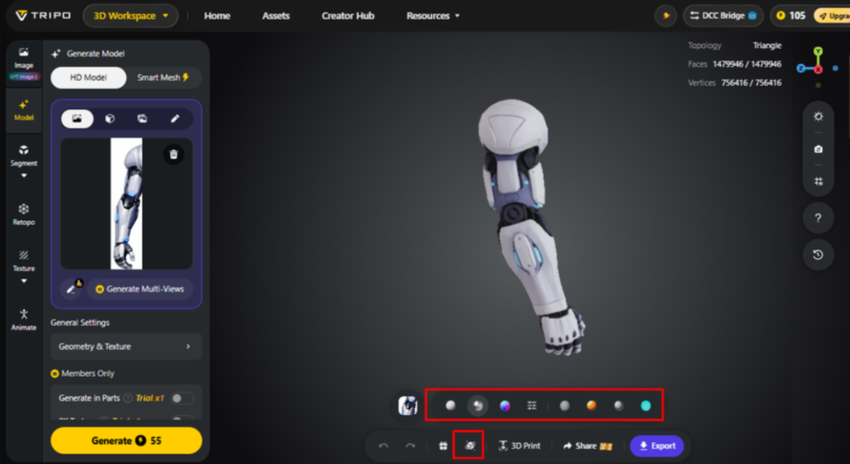
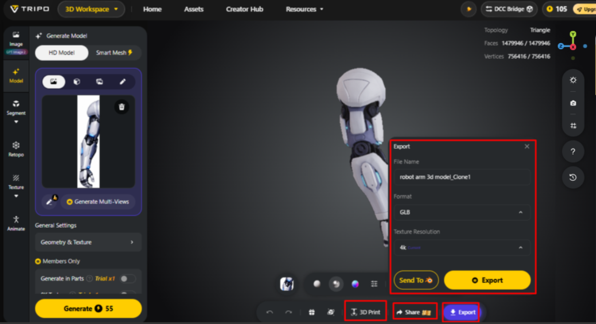
- After generation, use the available display modes to inspect your model. You can choose Wireframe Mode, White Model View, Texture View, Shader, or HDRI. For additional improvements, simply click “Refine” from the bottom menu.
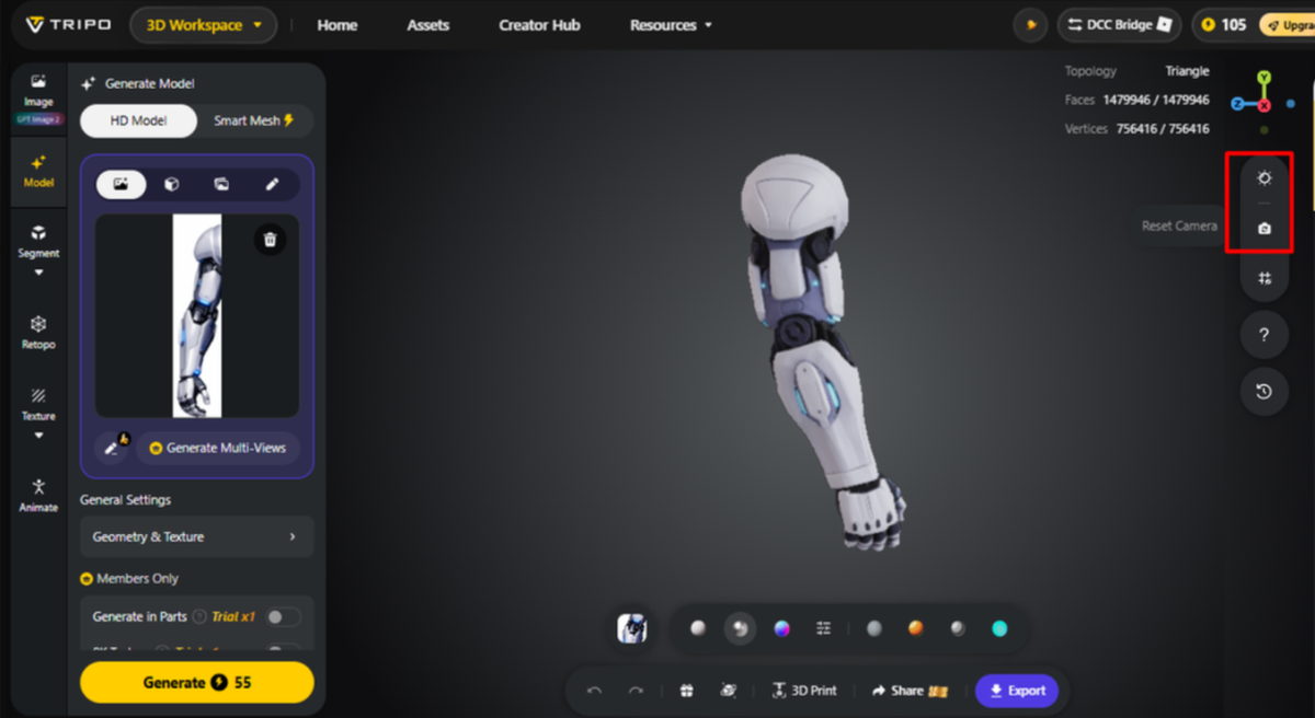
- You can modify “Environment Settings” and use “Reset Camera” to review the prototype from different angles.
- When you are satisfied with the asset, you can choose “3D Print” for physical output. You can also click “Share” to share the design directly.
- Click “Export” from the bottom menu to save the prototype. Select the required resolution, format, and filename, then click “Export” again to save the design to your local device.
Six Settings That Shape Rapid Prototype Asset Generation
- Detail Selection: Select detail based on visual complexity of prototype and need for structural representation. A more detailed geometry level can be used to model more complex shapes, whereas lower levels can be used for simpler shapes for easier editing later.
- Polygon Count: Specify a number of polygons commensurate with the geometric detail and downstream uses. Reduced counts can enable rapid iteration when complex surfaces offer little prototype value to explore.
- Texture Resolution: Choose 2K, 4K or 8K depending on the visual inspection and output requirements. Texture resolution becomes more important if it is a very important factor in the visual assessment of the prototype.
- Topology Choice: Use quad or triangle topology, depending on the editing and downstream workflow needs. The topology has an effective impact on the behavior of the mesh during the refinement, deformation and subsequent modeling operations.
- Part Separation: Separate parts for inspection or adjustment by using Generate in Parts. Logical separation can make components easier to change prior to an efficient combination of an editable prototype asset later.
- Model Version: Choose which Tripo 3D versions are available based on workflow, speed and quality. Each version offers a unique set of generation properties; selection should be carefully based on project priorities.
Using Low-Poly Geometry For Quicker Iterations
Structured low-poly geometry can enable faster edits in early prototype development and design exploration. With simplified meshes, proportion changes, component tweaks and material previews can be managed efficiently. Polygon control is important in games, visualization, printing and interactive applications where there are varying technical requirements. There is a text to 3d model workflow which allows for concept exploration and image references for guidance. Low-poly output is still valuable when the prototype is about silhouette, placement and overall proportions. When surface curvature or the structure of components is to be represented more closely, more detailed geometry can be used.
Refining Prototype Shapes Before Sharing Or Exporting
Look at important shapes before sharing or exporting, without being distracted from geometry by surface textures. Solid View can surface surprising thicknesses, proportions, missing openings and irregular component boundaries. When further enhancement is needed after detailed review, Refine can be submitted to improve geometry detail and texture quality; this typically takes 1–7 business days, and the refined model automatically replaces the original asset in your library. Different environment settings and camera controls are used to analyze surfaces under various viewing conditions during inspection. Share can be used for design review, and 3D Print can be used for physical prototype evaluation as appropriate. If external software will be used to work with the editable prototype asset after inspection, export should be used.
Moving Prototype Models Into Broader Design Workflows
The export format should be chosen based on the intended next step, since different formats are suited to different visualization and workflow needs. USD is widely used in film, VFX, and other USD-based pipelines for exchanging scene and geometry data. OBJ is a common file format that supports transferring meshes and related geometry and material data between software. FBX is an overall efficient format for workflows that include animation, scene exchange, and other digital content pipelines. GLB is a file format that efficiently stores geometry and other scene information for interactive visualization on the web. STL is used for many processes in the additive manufacturing workflow, based on surface geometry, and topology should be inspected before export. For 3D printing, 3MF can effectively carry additional manufacturing information within supported 3D manufacturing workflows. After importing, check the scale, normals, topology, materials, and component separation in the receiving software.
Conclusion
Image selection, generation, geometry control, inspection, and export form one connected prototype workflow. Each stage affects how faithfully visual references become drafts for subsequent design decisions. Start with simple references, then choose settings based on geometry, texture, and downstream needs. Review the model from multiple viewpoints, and only accept proportions and key part relationships after careful checking. If important structures come out wrong, adjust the inputs or settings and run another full prototype iteration. This is a practical cycle for turning early visual concepts into usable 3D assets without unnecessary modeling complexity.